Intake, outlet and Equilibrium-Valve
Watt’s very early engines until 1778 had only two valves. There was no intake valve, the steam from the boiler always pressed on to the upper side of the piston.
I would like to quote the description, which John Farey published 1827 in his book “A Treatise on the Steam Engine”. James Watt had died 8 years earlier. You have to take your time to read Farey’s book, it’s not really easy to read today, but most of the suceeding authors name him as a source (there was even a well known german professor, who took pictures and text from Farey, without annoying his readers with naming his reference …).
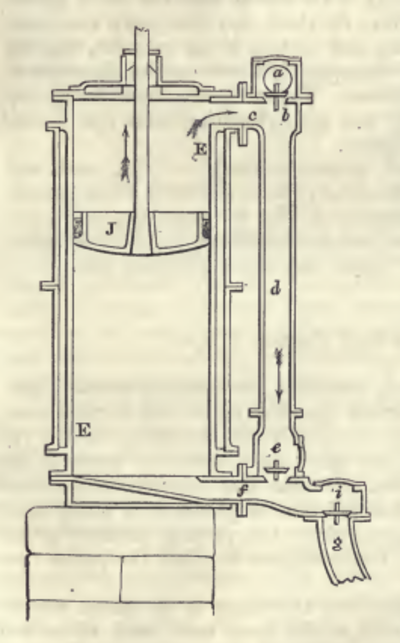
Pictures 1 and 2 are from Farey’s book. Picture 1 shows the mentionend 2 valve engine type. Picture 2 presents the 3 valve engine. This is what Farey writes on pg. 333 / 334 (Slightly shortened, remarks in [ ] by me):
Improved Form of Mr. Watts Engine, 1778. ... he [Watt) afterwards adopted another arrangement of the parts, in which the steam for the supply of the cylinder does not pass through the steam-case, but enters from the steam- pipe, through a valve immediately into the top of the cylinder ; and although the steam-case has a communication with the boiler, the steam which is admitted into it is only for the purpose of keeping up the heat, and preventing any condensation of the steam within the cylinder. ... The cylinder E E is fitted with its piston J, and is closed at top by the cover, which is screwed to the top flange of the cylinder itself ... The steam is brought from the boiler to the cylinder by the pipe a ... b is the regulating or throttle-valve in that pipe, and c the communicating passage into the top of the cylinder, immediately beneath the valve, so that the steam has constant admission through this valve into the top of the cylinder, and presses upon the piston, in such quantity as the constant opening of the regulating-valve b will allow. d is the steam-pipe, which descends to the bottom of the cylinder, for the purpose of admitting steam into the bottom of the cylinder, when the piston is to ascend ; and e is the equilibrium-valve [equilibrium = balance], which opens or shuts that communication at pleasure : i is the exhausting-valve, which being opened when the equilibrium valve, e, is shut, allows the steam to pass off through the eduction-pipe g to the condenser, which is on a similar construction to that already described ; but it is provided with an injection-valve, to admit a jet of cold water to flow into the condenser, so as to cool the steam, and produce the vacuum therein. The operation of this engine is as follows : Suppose the piston J to be drawn up to the top of the cylinder by the counterweight, and all the parts to be filled with steam, except the eduction-pipe g, and the condenser and air-pump, which are supposed to be exhausted, the equilibrium-valve e, and the exhausting-valve i, are shut. Now, if the exhausting-valve i is opened, the steam contained in the lower part of the cylinder, beneath the piston J, will pass by its own elasticity through the valve i, and rush into the vacuous space in the eduction-pipe g and condenser ; and being met there by the jet of cold water, the steam is cooled and condensed, so that the vacuum in the condenser is maintained, notwithstanding the rush of steam which is admitted into it ; consequently the steam continues to flow out of the cylinder, till none remains beneath the piston, or only a very rare vapour, which offers scarcely any sensible reaction to the steam above the piston, which is continually pressing it downwards. The piston is therefore put in motion, and begins to perform its working stroke, as soon as the steam is exhausted from the cylinder, and it continues to descend, till it arrives near to the bottom of the cylinder: the exhausting-valve i is then shut, and the equilibrium-valve e is opened by the working gear ; this allows the steam from the top of the cylinder to enter by the steam-pipe d through f, into the bottom of the cylinder, as is shown by the arrows, so as to press upwards beneath the piston J, with the same elasticity as the steam from the boiler presses downwards upon the upper side of the piston ; for there now is an open communication through c, d, e, and f, between the top and bottom of the cylinder, whereby the piston is placed in equilibrio, and is consequently drawn up by the counterweight [pump], until it arrives at the top of the cylinder. The returning stroke being thus completed, the equilibrium-valve e is shut, and the exhausting-valve i is opened again, to make another working stroke as before.
So far Farey in 1827.
Valve Gear
Dickinson and Jenkins quote Watt in their definite book 1927:
I find it will be best to have two Y-shafts and two loggerheads [i.e. tumbling bobs], that is one to each regulator.
This quote may be found in the context of the Wheal Busy Engine, presumably 1777, the remark in [] is in the book.
They summarize like so:
This type of gear, which we have termed the “wiper gear”, continued to be made for some years. In 1783 a new arrangement was devised, in which the connection between the arbors and the valve spindles was made by links and levers. This form we have called the “linkage gear”; it continued to be made, for the rotative as well as for the pumping-engines, after the year 1800;
So this makes clear that the Smethwick Engine originally was fitted with the “Wiper gear”. Unfortunately no such gear can be found today on a machine. The Lap Engine and it’s wonderful moving copy in the “Deutsches Museum Munich” utilize the “linkage gear”. So the model engineer’s only source is Dickinson.
The oldest existing relevant drawing is for Peter Colevile’s Engine from end of 1776. The engine started operation in the beginning of 1778. Picture 3 shows the drawing. The description in “James Watt and the Steam Engine”, pg. 179-181 follows:
The Wiper Gear
It is desirable to say, as briefly as possible, what the gear was required to do. The first engines, with an open—top inner cylinder enclosed in an outer cylinder, had but two valves, one to admit steam from the jacket space to the lower end of the inner cylinder below the piston, and the other to allow the steam to escape from the cylinder to the condenser. When the outer cylinder was replaced by a jacket, put on in segmental panels, and a lid was fitted to the working cylinder, a pipe had to be provided to convey steam from the top of the cylinder to the bottom ; at the top of this pipe was mounted a third valve which was worked to admit and cut off the supply of steam from the boiler. This valve was called the ‘top regulator’ ; the valve that admitted steam below the piston was the ‘steam regulator’, or ‘middle regulator’, and the remaining valve was the ‘exhaustion regulator’.
In order, to avoid confusion in what follows, the valve that admits steam from the steam pipe to the engine is termed the steam valve, and, inasmuch as it serves to put both sides of the piston in equilibrium, the ‘middle’ or ‘steam’ regulator is called the equilibrium valve.
In addition to these valves, there was the injection valve to be opened and closed at each down—stroke of the engine.
When the piston was at the top of the cylinder, in order to make the down— stroke, the steam valve (if one was provided), the exhaust valve, and the injection valve required to be open ; and the equilibrium valve shut. Before the piston reached the bottom of the cylinder the first three valves had to close, and then the equilibrium valve had to open for the up—stroke. Watt laid down the rule that the exhaust valve was to be shut when the piston had nearly completed its down— ward movement and a little before the equilibrium valve was opened, and that the injection valve was to be opened an instant before the exhaust valve and to be shut soon after the piston began to move down.
It was requisite to contrive the gear so that the valves could be worked either by hand or automatically at will ; moreover, it was necessary to be able to close both valves, equilibrium and exhaust, at once, in order to stop the engine, and to have both open at once for blowing through at starting.
The earliest existing drawing of the wiper gear is that for Colevile’s engine, an engine with open—top working cylinder and two valves only ; it is reproduced in Plate XLVIII. The upper set of mechanism is for the equilibrium valve, and the lower, shaded, set is for the exhaust and injection. The upper mechanism consists
of an arbor with a ‘loggerhead ’, or tumbling bob J, a bent handling—arm K, and a horn or curved wiper L which bears on the upper surface of a straight arm secured on the valve spindle. The lower mechanism has a similar arbor, handling—arm, and wiper, and, in addition, a detent engaging a pivoted catch provided with a tail N standing in the path of a peg on the plug-tree ; to the detent is suspended a rod H carrying a weight ; the wiper bears on the under side of a straight arm on the exhaust valve spindle.
The parts are shown in thick lines in the position which they occupy when the piston is at the bottom of the cylinder, with the equilibrium valve open and the exhaust and injection valves shut ; the exhaust valve is on the same side of its spindle as the arm, the equilibrium valve is on the opposite side of its spindle.
As the piston, and with it the plug-tree, moves upward and approaches the top of its stroke, a peg on the plug-tree acts upon the tail N of the catch and frees it from the detent ; the weighted rod H then pulls round the arbor, the wiper raises the arm on the valve spindle and opens the exhaust valve, and by means of a cord it opens also the injection valve. The parts then assume the position indicated by thin lines. Upon the descent of the piston a peg in the plug—tree acts upon the handling—arm, first along the part A, B, and then along the part B, G, and restores it to the position shown; its movement is accompanied by that of the wiper which allows the injection valve to close; the exhaust arm follows the wiper and the exhaust valve closes. The downward movement of the handling-arm also raises the detent and the weighted rod H, and the detent re-engages with the catch, now free, as the peg has moved clear of its tail.
In short, the exhaust valve, with the pressure in the cylinder above it, and the vacuum in the condenser below it, is opened by the descent of a weight, which weight is held by a self—acting catch until this is tripped by the upward movement of the plug—tree ; it is closed by its own weight and that of the arm on its spindle upon the downward movement of the plug-tree, and at the same time the weight for, opening is raised and re-engaged with its catch. It is interesting to note that Watt used the trip mechanism to open the valve, whereas in modern practice it is used to close the valve.
If it should happen that the peg B does not depress the handling—arm far enough to allow the valve to close, an additional peg F may be inserted in one of the holes of the inner row in the plug-tree, which, acting upon the arm nearer to its axis, ensures sufficient movement. The extent of the opening of the valve is adjusted by a wedge or other device to limit the descent of the weighted rod H. …