You may not recognize the beam of my fifth model with a beam at once. It is an angle lever, the engine is known as Bell-Crank-Engine. The name Bell-Crank derives from its first use, changing the vertical pull on a rope to a horizontal pull on the striker of a bell, used for calling staff in large houses or commercial establishments, see picture 1.
I collected various pictures and details regarding the historical Bell Crank Engine here.
When I built my models of the Drop Valve Engine and the Smethwick Engine I had hard times to get them running. So this time I wanted to follow a proven plan. Antony Mount published drawings of a bell crank model in his book “Historic Engines Worth Modelling Vol. 1”. The drawings as well as Mount’s text refer to a set of castings. Of course they are not metric. Of course I wanted to build from bar stock and metric - but I considered that to be doable.
The model does not seem to have been built frequently, at least in Mount’s version, i.e. with condenser and cistern. Dr Jo Thoms described the build of her casting set in the Model Engine Maker Forum. She mentioned there, that in the first casting run ten sets were made and that it took ten years to sell these. A second run was done but it did not have the quality needed.
A really attractive bar stock model of a Bell Crank was built by Carlos Kretz from Rosario / Argentina. Obviously he followed the pattern of the blowing engine Dickinson mentioned.
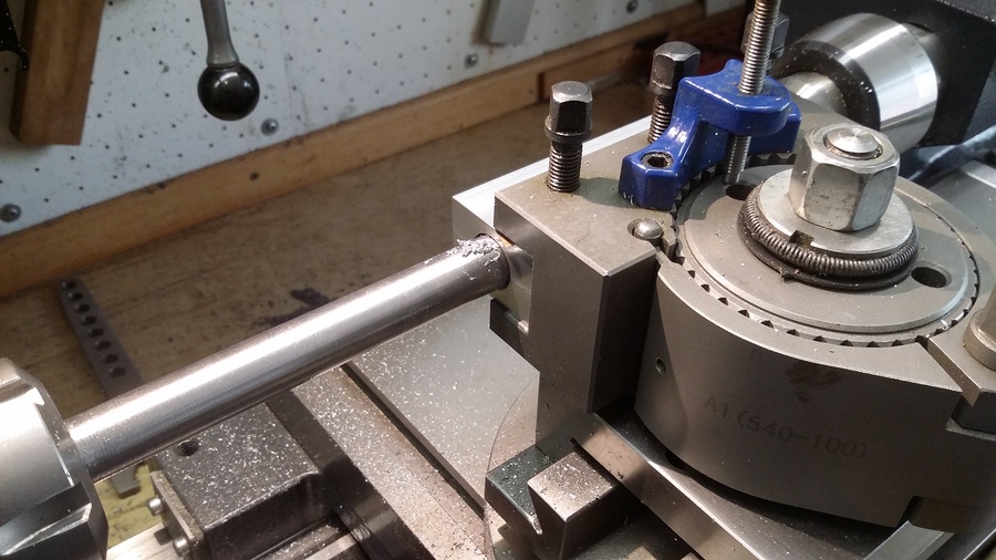
I started with the cylinder (Picture 2). Its made from aluminum with a brass liner pressed in. I reduced the bore compared to Mount’s plan. The slot will take the valve body. Despite Mount describes a D-valve in his plans, I changed my mind and again took a brass pipe. Picture 3 shows the boring of the valve body with a shop made boring bar. The outer contour was done on the milling machine using the ARC function of my SINO DRO. According to the Manual there is a Smooth ARC Function and a Simple ARC Function. But the firmware provides only the Simple ARC Function. After I managed to understand the manual I came up with a good result. Picture 4 shows the valve after finishing the milling operation. The completed body can be seen in picture 5.
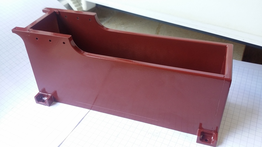
The cistern is made from aluminum boards. These have been glued and screwed. The feet to fasten the cistern on the mounting plate as well as the feet to fasten the crank bearings have been cut out of the respective board - all my experiments to solder aluminum failed … In picture 6 the part can be seen after coating.
The flywheel (picture 7) is made from cast iron (200 ø) with attached webs.
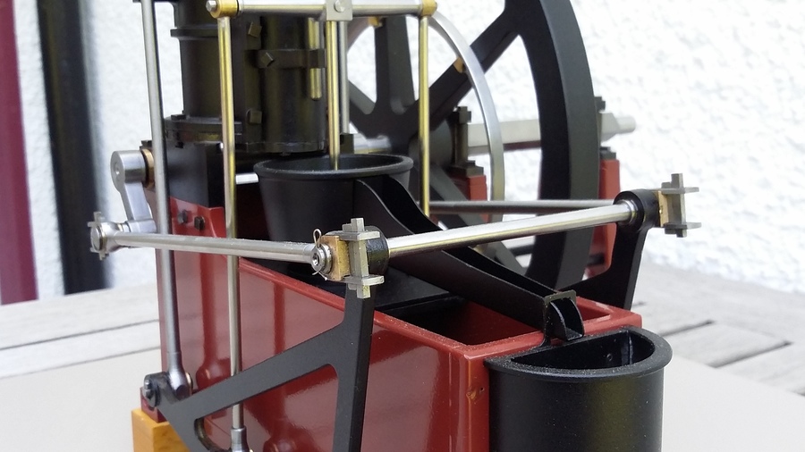
In picture 8 you can see the finished bell crank in place with all bars connected. I masked the cistern for the sake of a clearer picture.
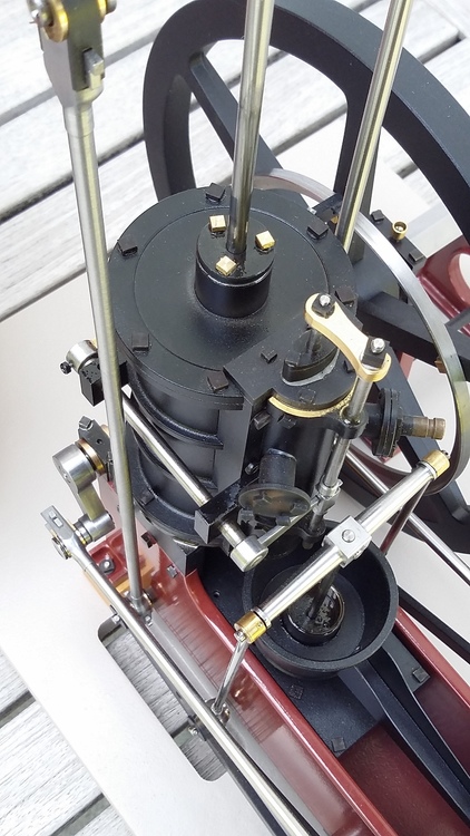
The other pictures are various views of the finished model.
To see the model running is still a great pleasure for me. Look at this video if you want to understand why !
Version 20.6.2016