My fourth model with a beam has a very prominent historical pattern: The Smethwick Engine constructed by James Watt. It started work in June 1779 and was used to pump water back to the Smethwick locks (hence the name).
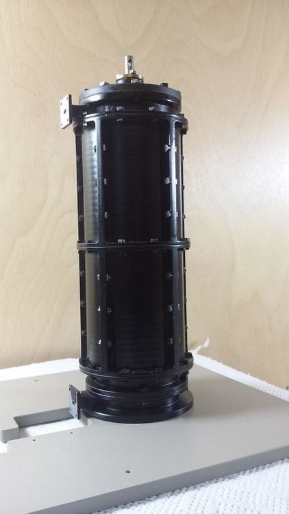
The Smethwick Engine is one of the very few engines, which have been preserved. It remained on its original site until 1897, see picture 1. It then was reerected on another site and according to Dickinson worked under steam at the commemoration of the centenary of James Watt’s death in 1919. Today it is on display at Thinktank, Birmingham Science Museum and steamed occasionally, see picture 2.
David K. Hulse presents the Smethwick Engine in his book “The Early Development of the Steam Engine”. This way I became aware of this engine. He also built a very detailed model in 1:16. Fortunately he was in close contact with Dr Jim Andrew, who has been a member of the Birmingham Science Museum and had intimate knowledge about the machine. Dr Andrew also published papers regarding the Smethwick Engine.
When I started my model, quite a few questions came up. Unfortunately nobody was willing to share, so I ended up with a few photos, a drawing by Farey and the book of Dickinson and Jenkins (Visiting the Birmingham Science Museum was no option so far). I have collected some details here.
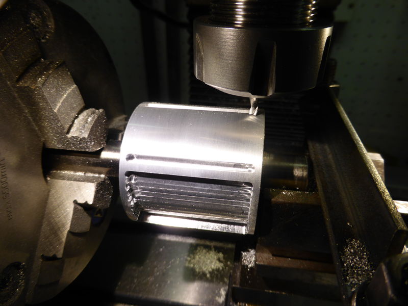
The cylinder was one of the first building blocks. The very early machines were all fitted with a steam jacket (basically a outer cylinder enclosing the inner steam cylinder, the space between the two filled with steam), because Watt thought this would enhance the engine’s power. I wanted to show this steam jacket in my model.
During it’s long working life the Smethwick Engine has got not only a new cylinder (1803, without steam jacket) but also new valves and a new valve gear. The valve gear, which can now be seen in the Thinktank Museum, has been fitted less than 30 years ago. Dr Andrew wrote, that 1919 the engine might have been driven manually.
According to John Farey Watt started in 1778 to fit his engines with a third valve, an intake valve. Until then only two valves had been used, so the fresh boiler steam always pressed on the upperside of the piston. You may find more details here.
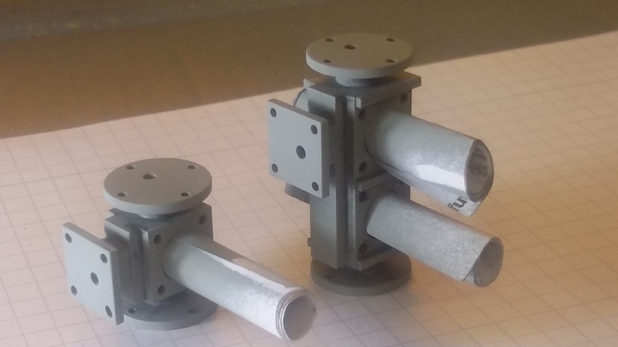
I wanted to show pump, condenser and air pump in my Smethwick Engine model. Normally, these components can hardly be seen. So I decided to make the basement as transparent as possible.
Unlike the typical pump engine for collieries the beam of the Smethwick engine lay on its own supporting stand. So the pump was completely inside the engine house.
Another really critical part can be seen in the pictures: In the old books it is called Loggerhead oder Tumbling Bob. It is a weight at the end of an arm, connected to the steam valve and triggered by the beam, when going up and down.
This part has a difficult to control vibration behavior. I tried hard to drive the model with two valves. After a long series of experiments with quite a few different valves and tumbling bobs I finally had to give up. Now the model is driven with one valve, which connects the piston with compressed air in one position and to the atmosphere in the other. This of course implies, that the piston is forced up only by the weight on the pump side, which in turn means that compression must not be too high. Air consumption is high. I have seen a nicer movement, but for the time being all my patience is used up.
Here is a video of the model:
https://www.youtube.com/watch?v=B89btYtkk8A
And here you can see the original in the Thinktank Birmingham:
https://www.youtube.com/watch?v=-vbDSXnM1mE
Here can be seen rather clearly, that the new constructed valve gear has been designed like it may have been in 1803. In “James Watt and the Steam Engine” by Dickinson and Jenkins one can read in detail, how much the valve gear changed in this early development period. Further details may be found here.
[Posted May 2015]
Addendum May 2016: The Smethwick Model, a boy called Benni and the Niephaus rocker switch
A few months ago Benni, a little boy, played with my Smethwick Engine model. Unfortunately since then the engine did not work any longer. I didn’t succeed in finding the right settings again and finally packed away the model. Recently Gerd N. came up with an interesting idea: What about breaking up the fixed coupling between the loggerhead and the valve spindle ? He suggested to add two pins to the loggerhead, which should trigger a rocker switch fixed to the valve spindle, see the last picture. This idea made me set to work again.
Again it took really time, but finally the model is running again. Unlike the first version now two valves are engaged. I finally had to come up with new, faster acting valves. With the shown rocker switch the model’s motion now seems appropriate:
Thank you Gerd !
On Benni’s next visit I will keep an eye on my model - the Smethwick Engine in 1:24 is still a very sensible engine. It demanded a great deal of patience and showed me the borders a model engineer can hit with an engine.
Version 31.5.2016